Virtualization, Cloud, Infrastructure and all that stuff in-between
My ramblings on the stuff that holds it all together
How does an HP Fibre Channel Virtual Connect Module Work?
Posted by on April 9, 2008
Techhead and I have spent a lot of time recently scratching our heads over how and where fibre channel SAN connections go in a c7000 blade chassis.
If you don’t know, a FC-VC module looks like this, and you install them in redundant pairs in adjacent interconnect bays at the rear of the chassis.

You then patch each of the FC Ports into a FC switch.
The supported configuration is one FC-VC Module to 1 FC switch (below)
![clip_image002[6]](https://vinf.net/wp-content/uploads/2008/04/clip-image0026.jpg)

Connecting one VC module to more than one FC switch is unsupported (below)
![clip_image002[8]](https://vinf.net/wp-content/uploads/2008/04/clip-image0028.jpg)

So, in essence you treat each VC module as terminating all HBA Port 1’s and the other FC-VC module as terminating all HBA Port 2’s.
The setup we had:
- A number of BL460c blades with dual-port Qlogic Mezzanine card HBAs.
- HP c7000 Blade chassis with 2 x FC-VC modules plugged into interconnect bay 3 & 4 (shown below)


The important point to note is that whilst you have 4 uplinks on each FC-VC module that does not mean you have 2 x 16Gb/s connection “pool or trunk” that you just connect into.
Put differently if you unplug one, the overall bandwidth does not drop to 12Gb/s etc. it will disconnect a single HBA port on a number of servers and force them to failover to the other path and FC-VC module.
It does not do any dynamic load balancing or anything like that – it is literally a physical port concentrator which is why it needs NPIV to pass through the WWN’s from the physical blade HBAs.
There is a concept of over-subscription, in the Virtual Connect GUI that’s managed by setting the number of uplink ports used.
Most people will probably choose 4 uplink ports per VC module, this is 4:1 oversubscription, meaning each FC-VC port (and there are 4 per module) has 4 individual HBA ports connected to it, if you reduce the numeber of uplinks you increase the oversubscription (2 uplinks = 8:1 oversubscription, 1 uplink = 16:1 oversubscription)

Which FC-VC Port does my blade’s HBA map to?
The front bay you insert your blade into determines which individual 4Gb/s port it maps to and shares with other blades) on the FC-VC module, its not just a virtual “pool” of connections, this is important when you plan your deployment as it can affect the way failover works.
the following table is what we found from experimentation and a quick glance at the “HP Virtual Connect Cookbook” (more on this later)
| FC-VC Port | Maps to HBA in Blade Chassis Bay, and these ports are also shared by.. |
| Bay3-Port 1, Bay-4-Port 1 | 1,5,11,15 |
| Bay3-Port 2, Bay-4-Port 2 | 2,6,12,16 |
| Bay3-Port 3, Bay-4-Port 3 | 3,7,9,13 |
| Bay3-Port 4, Bay-4-Port 4 | 4,8,10,14 |

Each individual blade has a dual port HBA, so for example the HBA within the blade in bay 12 maps out as follows
HBA Port 1 –> Interconnect Bay 3, Port 2
HBA Port 2 –> Interconnect Bay 4, Port 2
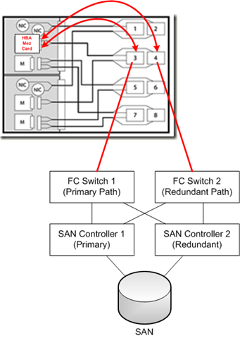
Looking at it from a point of a single SAN attached Blade – the following diagram is how it all should hook together
Path Failover
Unplugging an FC cable from bay 3, port 4 will disconnect one of the HBA 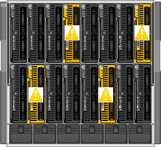 connections to all of the blades in bays 4,8,10 and 14 and force the blade’s host OS to handle a failover to its secondary path via the FC-VC module in bay 4.
A key take away from this is that your blade hosts still need to run some kind of multi-pathing software, like MPIO or EMC PowerPath to handle the failover between paths – the FC-VC modules don’t handle this for you.

FC Loading/Distribution
A further point to take away from this is that if you plan to fill your blade chassis with SAN attached blades, each with an HBA connected to a pair of FC-VC modules then you need to plan your bay assignment carefully based on your server load.
Imagine if you were to put heavily used SAN-attached VMWare ESX Servers in bays 1,5,11 and 15 and lightly used servers in the rest of the bays then you will have a bottleneck as your ESX blades will all be contending with each other for a single pair of 4Gb/s ports (one on each of the FC-VC modules) whereas if you distributed them into (for example) bays 1,2,3,4 then you’ll spread the load across individual 4Gb/s FC ports.
Your approach of course may vary depending on your requirements, but I hope this post has been of use.

There is a very, very useful document from HP called the HP Virtual Connect Fibre Channel Cookbook that covers all this in great detail, it doesn’t seem to be available on the web and the manual and online documentation don’t seem to have any of this information, if you want a copy you’ll need to contact your HP representative and ask for it.


Pingback: HP Virtual Connect Modules Demystified |
Pingback: Great Article on HP Fibre Channel VirtualConnect - blog.scottlowe.org - The weblog of an IT pro specializing in virtualization, storage, and servers
Pingback: My Etherealmind · Don’t tell me iSCSI is complicated if Fibrechannel looks like this
This is a great write-up on how VC works. The Virtual Connect (ethernet and fiber channel) cookbooks are posted on http://www.hp.com/go/bladeconnect.
Create an ID and login. Then look in the VC Interest List for files to download.
re: “Unplugging an FC cable from bay 3, port 4 will disconnect one of the HBA connections to all of the blades in bays 4,8,10 and 14 and force the blade’s host OS to handle a failover to its secondary path via the FC-VC module in bay 4.”
I’m not sure that is entirely correct (anymore?)… We were just playing with this in our lab, and when we unplugged one port, that Virtual Connect module remapped the connected ports as if only 3 ports were part of the fabric. So where the blades in bays 4,8,10, and 14 were connected to the FC uplink in bay 3, port 4, they would now be connected something like this (not 100% sure what the algorithm is, just that it’s based on having three ports available):
blade 4 – bay 3, port 1
blade 8 – bay 3, port 2
blade 10 – bay 3, port 1
blade 14 – bay 3, port 2
It may have been added as a feature of the new firmware, version 1.31. Not sure as we never performed that test on earlier firmware.
Anyway, definitely something to be aware of. Our understanding was that it behaved as you described, and we had mapped VSANs to SAN switchports based on that behavior, so this remapping thing didn’t work so well for us… We’re now trying to figure out how to support this with a different SAN architecture…
Thanks,
Interesting, will see if I can try this out in the next couple of weeks with more recent firmware
Thanks
Most of this article is not applicable if you use a recent firmware, like a previous poster said the FC uplinks are dynamicly assigned to the blades so unplugging an uplink does not fail any paths.
FC traffic is also load balanced between all available paths (if configured).
It’s now also possible to attach one module to more than one fabric.
Yes, I belive that is the case with newer firmware; which is a massive improvement.
simple question.
why should i use vc instead of san-switches?
will it ease my life,budget ?
simple question
why use vc ?
will it ease my life,budget ?
In this instance we used VC modules as they alias the WWN of the HBA inside a blade, so the storage admins can setup the zoning, switches etc. once and if we have to swap out a blade due to hardware failure the FC modules make it transparent and there are no changes required on the SAN side as we always map to “virtual” WWN’s owned by the VC modules.
think of it as NAT, but for fibre-channel 🙂
I belive the same sort of principal applies for the VC-Ethernet modules.
HTH
could you please tell me what are the pros and cons when using VC versus no VC (SAN Switch,Ethernet Switch) ?
for example
with VC we can achieve …..
but we can not have ….
with SAN/Ethernet (non VC)
we can…
but we can not….
TIA
sorry for delay in approving your comment, it was stuck in my spam queue 😦
in a nutshell;
Virtual Connect = abstraction, configure your SAN zoning and LUN masking once by using the virtual WWN of the VC modules; if you swap out the blade and/or HBA mezzanine card.
Integrated blade switches = more switches in your DC, more spanning tree and more management and you need to manage a core, distribution and edge switch topology.
If VM’s do a lot of talking to each-other within the same chassis, then maybe switches rather than VC are a better approach – keep all traffic within the chassis rather than trunking out to external switches and back in again – VC modules do have private networks but they are not L3 routeable to the outside world IIRC
VC always needs external switches, so extra cost but easy swap out and configure once.
Pingback: Hardware Vendors… release the emulators to the masses PLEASE!! « Virtualization, Windows, Infrastructure and all that “stuff” in-between
Pingback: Confused by HP Flex10 Design for vSphere « Virtualization, Cloud, Infrastructure and all that stuff in-between
Pingback: Resources for HP c-class blade and EVA Design for vSphere 4 « Virtualization, Cloud, Infrastructure and all that stuff in-between
VC does need external switching. and VC compliements Virtualization Technology, however its not a replacement of any Hypervisor in the market.
VC along with FlexFabric gives you a 10Gbc Pipe that can be split to multiple 1Gb NICs and also to a 4gbps FC fabric.
The advantage :
Can control the Bandwidth according to the traffic on any given NIC and the remaining bandwidth can be worked upon to the FC path.
Aviods Multiiple Cable Sprawling, since only single mode fabric is used and controlled. Hence even Management becomes easy.
Proliant Blades are enable on-board with 10Gb Bandwidth, hence you do not need additional mezzaine for your FC ( cost Saving).
Complimented by HP midplane technology of Serailizer and Deserailzer, this is one of the best in terms of performance !!
Hello,
Is this diagram still accurate? HP tech told us otherwise just recently. Thanks!
This is probably out of date now – best to check the latest cookbooks